


DSP Electronics
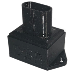
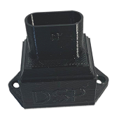
FLEX FUEL MODULE
To install our Flex Fuel Emulator Modules follow these 4 easy steps:
-Step 1, disconnect the vehicles battery
-Step 2, unplug the electrical connector from flex fuel sensor. It is also a good idea to clean and inspect your vehicles flex fuel electrical plug. Clean and remove debris to make a good connection. Dielectric grease is a good idea too. (leave the flex fuel sensor in place)
-Step 3, plug the electrical connector to the DSP emulator module and secure to vehicle.
-Step 4, reconnect the battery

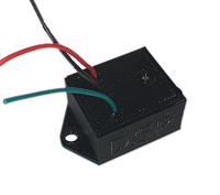
FUEL CUT Eliminator MODULE
To install our Fuel Cut Eliminatior Module follow these steps:
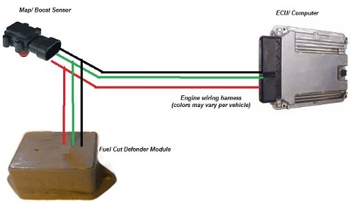
Splice into the existing wiring harness between the Map/Boost sensor and the ECU.
Reminder: Red is 5v+, Black is GND - , Green is SIGNAL OUT to ecu.
Make sure it is a good weather tight connection!
To adjust: Simply turn the screw clockwise to allow more boost, counterclockwise for less boost.
Splice into the existing wiring harness between the Map/Boost sensor and the ECU.
Reminder: Red is 5v+, Black is GND - , Green is SIGNAL OUT to ecu.
Make sure it is a good weather tight connection!
To adjust: Simply turn the screw clockwise to allow more boost, counterclockwise for less boost.
Click on picture to expand
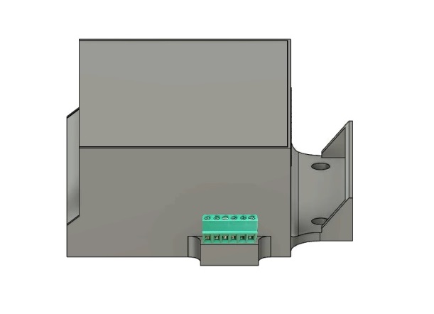
TIME ON DELAY MODULE
To install our Time on Delay Module follow these steps:
Connect the wiring below to your project.
Reminder: Red(+12v), Black (Ground or negative), Green (Relay Common), Orange (Relay N.O.), Yellow (Relay N.C.)
Connect the wiring below to your project.
Reminder: Red(+12v), Black (Ground or negative), Green (Relay Common), Orange (Relay N.O.), Yellow (Relay N.C.)
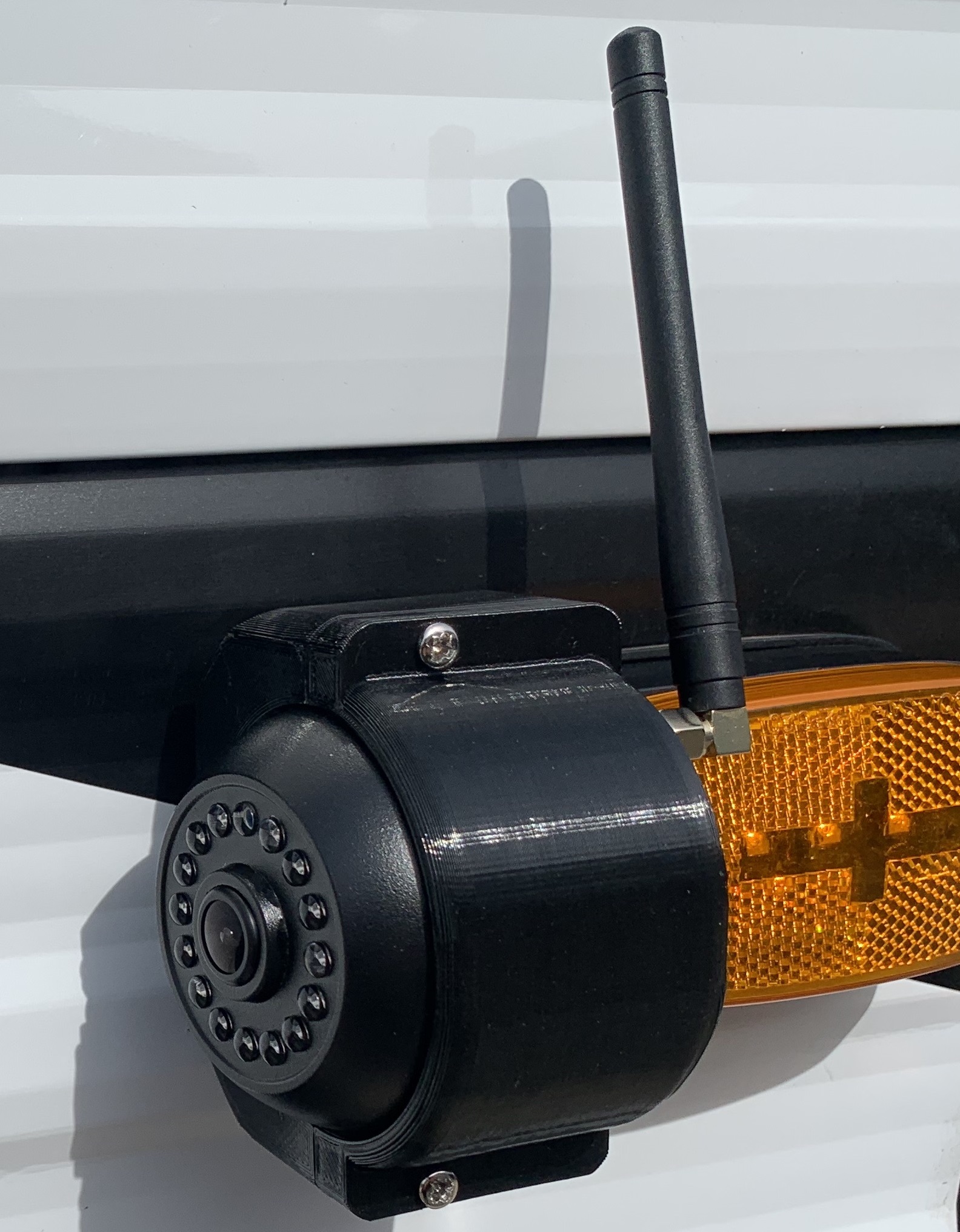
Camera Adapter
AUTO TRIM CONTROLLER

Not sure what type of controller you need?
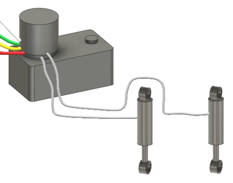
Hydraulic trim tabs do not usually have any wiring on the trim cylinders themselves, rather they have a metal or plastic line with fluid. They also will have a pump and fluid reservoir usually inside the hull of the boat. The lines or tubes from the pump will connect to the trim cylinders in the back of the boat. Example below.
Hydraulic trim tabs do not usually have any wiring on the trim cylinders themselves, rather they have a metal or plastic line with fluid. They also will have a pump and fluid reservoir usually inside the hull of the boat. The lines or tubes from the pump will connect to the trim cylinders in the back of the boat. Example below.
Electric trim tabs do not use any type of pump, they contain a motor built in them. They generally have 2 wires coming from them. They are often larger on the top of the cylinder where it contains the motor. Example below.
